
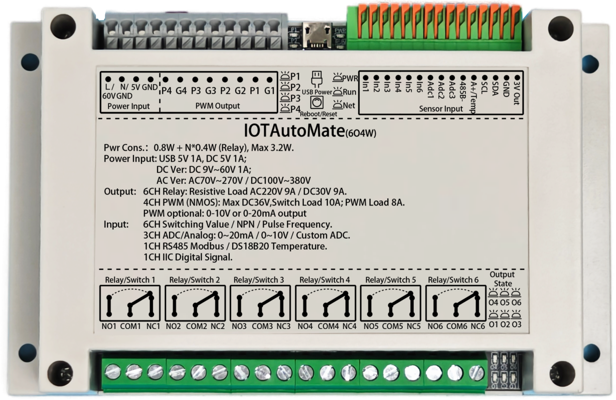
Interface Overview
1. Power Interface
AC Version (Optional): Connect AC 70-270V (47-63Hz) or DC 100-380V. No L/N distinction.
DC Wide Voltage Version (Optional): Supports DC 9-60V (Power >9W). L/36V terminal connects to positive, N/GND terminal to negative.
DC 5V Standard Version: This port is invalid.
Input Mode: For Standard DC 5V Version. DC 5V (Current >1A), GND connects to negative.
Output Mode: For AC / Wide Voltage Version, this port outputs 5V (Current <100mA), can power small sensors.
· Wiring Examples:
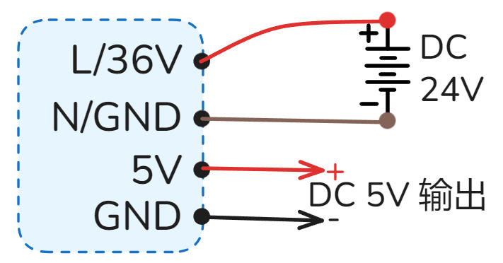 DC Wide Voltage DC 9-60V Power Supply
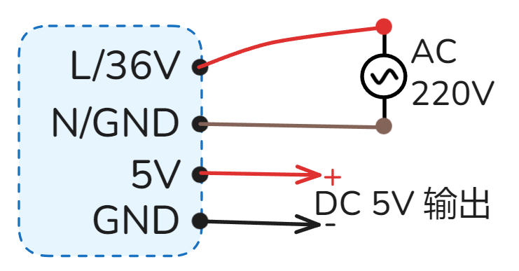 AC 220V / AC 110V Power Supply
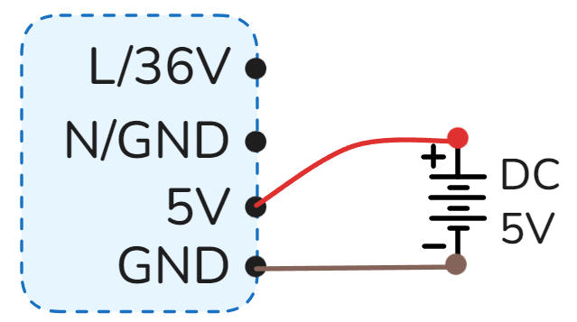 5V Power Supply
2. PWM Output
Uses N-MOS open-drain output, Pn port pulled up to DC 5V. Supports frequency control: 0.025Hz ~ 150kHz, duty cycle control: 0.00% ~ 100.00%, supports linear acceleration and deceleration control.
Port Definition: ·Pn represents PWM output positive, ·Gn represents negative (GND).
Load Capacity: Single channel supports max DC 36V 10A switching load or DC 36V 8A PWM load.
Commonly Used For: DC motor speed control, stepper/servo motor pulse control, servo angle, light brightness adjustment, inverter frequency, valve opening, etc.
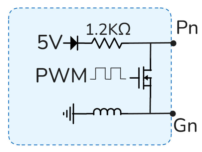 PWM Interface Simplified Internal Circuit
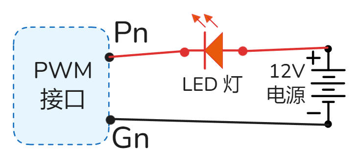 LED Brightness / DC Motor Speed Control
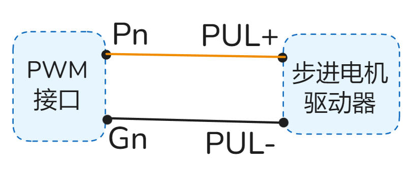 Stepper Motor Speed Control
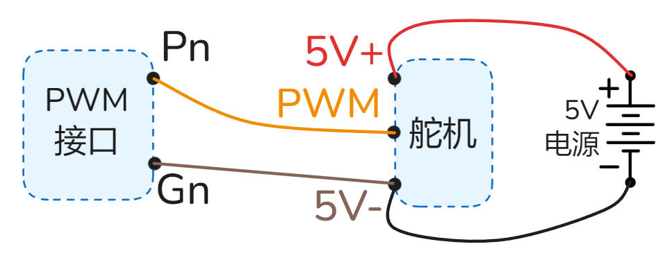 Servo Angle Control
Pn is output voltage positive, Gn is voltage negative, max load current is 10mA.
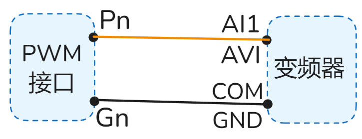 0-10V Inverter Control Wiring Example
Pn is current output port, Gn is current input port.
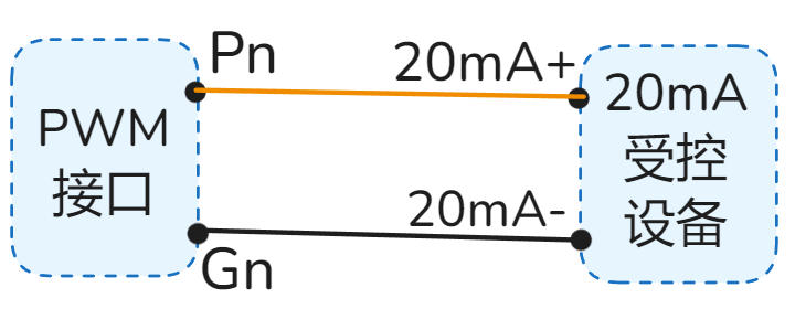 0-20mA Device Control Wiring Example
3. PWM Indicators
Real-time display of PWM1~4 channel output status. Can observe switching and brightness status.
·P1 represents PWM1 channel output status, P2 represents PWM2 channel output status, and so on.
4. USB Power Port
Micro USB (Old) / Type-C (New) interface, for convenient 5V power supply to the device, requires current > 1.5A.
Note: Please use high-quality cables to avoid voltage drop due to high resistance, causing insufficient power supply and device malfunction.
5. Reset Button
Device power cycle reboot.
Operation: Short press 7 times continuously: press 1s, release 1s each time.
Function: Restore factory settings, clear all user configurations, restore device to factory default state.
⚠️ Please use this function with caution.
In the App, enter the device details page, click "Reset" or "Reboot" button in the "Settings" interface.
6. Power/Run/Net Indicators
Always on indicates normal power supply.
Slow Flash (2s/time): System running normally.
Fast Flash (0.5s/time): Bluetooth connecting (App interacting).
Double Flash (2 fast flashes every 2s): MQTT version network connected.
Always On/Off: Running abnormally, please try to power cycle; if still abnormal, it may be a hardware fault.
Tuya WIFI Version: Fast flash=Waiting for pairing; Always on=Connected; Always off=Connection failed/Connecting.
Tuya 4G / 4G MQTT Version: Slow flash=Connected to base station; Always off=Searching or abnormal.
WIFI MQTT Version: Reserved (No actual function).
7. Switch/NPN/Frequency/Pulse Input
Supports Switch, NPN, Frequency, Pulse signal inputs.
Signal Features: Low level / Negative / GND signal is valid.
High Speed Counting: Supports 20kHz frequency input.
Voltage Withstand: Input port withstand voltage 1KV.
Relays, Buttons, Switches, PIR sensors, Limit switches, Photoelectric switches, Magnetic switches, Water level switches, Proximity switches, Infrared beam sensors, etc.
 Switch/Button Wiring Example
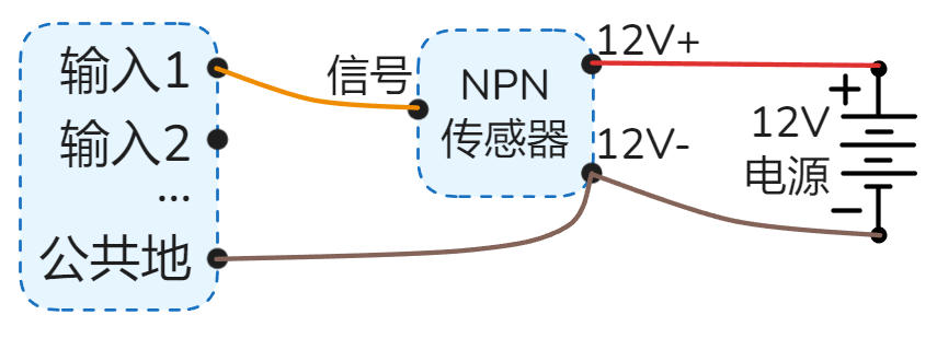 NPN Sensor Wiring Example
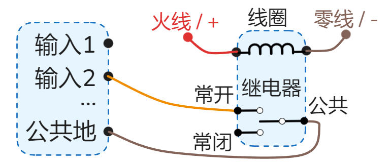 Relay as Input Wiring Example
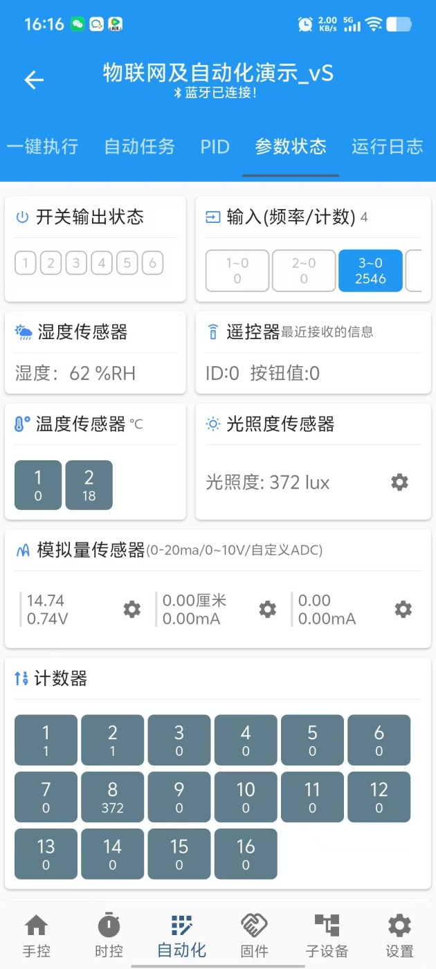
"3~0 2546"
means Input 3, current frequency 0Hz, accumulated pulses 2546.
8. Analog Input
Supports 0-20mA / 0-10V / Custom ADC etc. analog signal inputs.
Applicable Devices: Level transmitters, Pressure transmitters, Current transmitters, Temperature transmitters, Displacement sensors, Wind speed sensors, etc.
0-20mA Gear: Supports 0-20mA, 4-20mA, 0-40mA (New HW)
0-10V Gear: Supports 0-10V, 0-5V, 1-10V, 0-24V (New HW)
Custom ADC Gear: Supports 0-1.5V, 0-3V (New HW) voltage sampling
Device has a 3-position toggle switch on the side for different signal types.
As shown: Analog 1 is Custom ADC, Analog 2 is 0-10V, Analog 3 is 0-20mA.

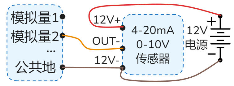
 2-wire 4-20mA Sensor Wiring
 3-wire 4-20mA or 0-10V Sensor
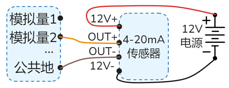 4-wire 4-20mA Sensor
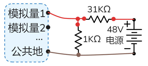 Detect 48V Battery (Custom ADC) - Divider to 1.5V

9. RS485/Termperature
Default Function: Supports DS18B20 temperature sensor, reading corresponds to "Temperature 1" in App.
Note: Sensor cable length suggested ≤ 2 meters; too long may cause interference and read failure.
When RS485 Option Selected: This port acts as RS485 A+ port, DS18B20 function unavailable.
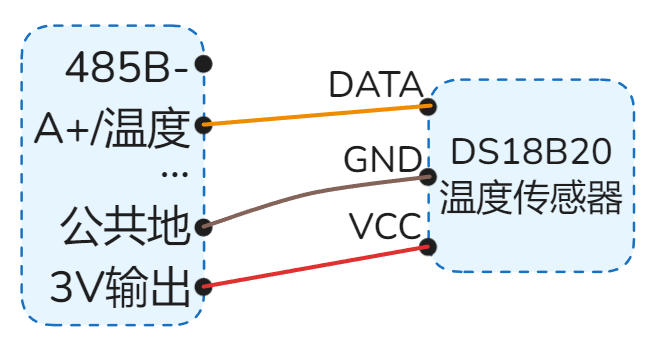 DS18B20 Temperature Sensor Wiring Example
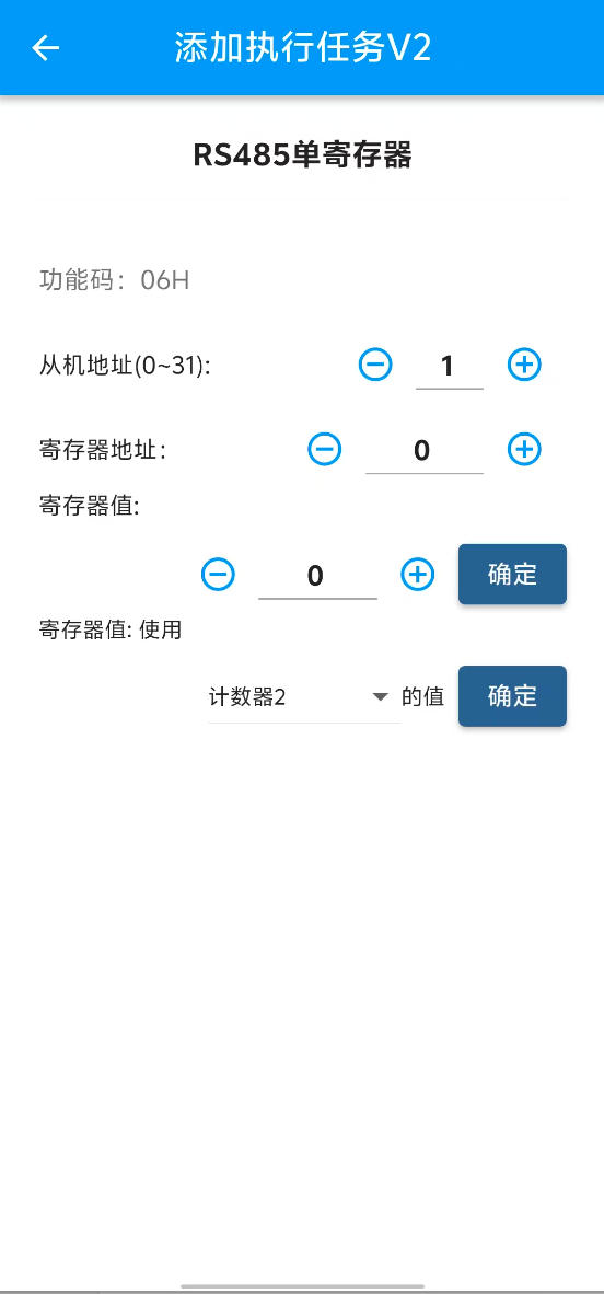
IOTAutoMate acts as RS485 Master, supports reading/controlling various RS485 Slave devices.
Protocol: Modbus RTU
Baud Rate: 1200 ~ 38400bps, Data bits: 8, Stop bits: 1, Parity: None
Read Function Codes: 01H, 02H, 03H, 04H
Write Function Codes: 05H, 06H, 0FH, 10H
Device Capacity: Supports up to 16 slaves. Reads 32 data registers and 32 status bits (Coils/Discrete).
Read Cycle: Auto-cycle read every 0.5 seconds.
Slave Address: Supports address range 1 ~ 31.
Supported Devices: PLC, HMI, Smart Meters, Weather Stations, Relay Modules, Servo Motors, Inverters, PH Sensors, Dissolved Oxygen Sensors, etc.
Correct Wiring Example:
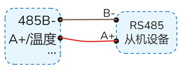 Single Device RS485 Wiring Example
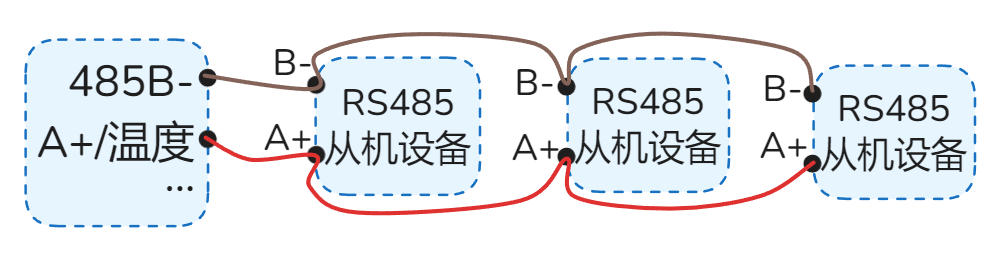 Multiple RS485 Devices — Daisy Chain (Bus) Wiring (Correct)
Not Recommended (Prone to Interferance) Wiring Examples:
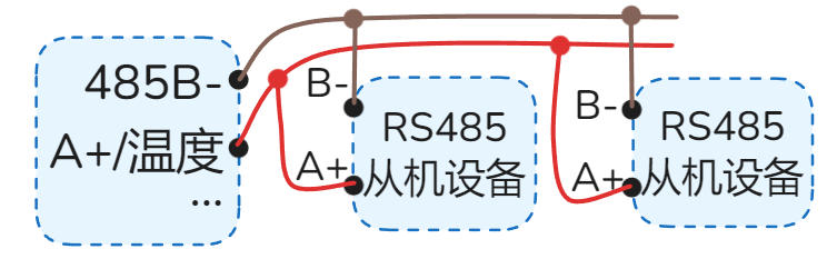 Multiple RS485 - T-Junction (Prone to Interference)
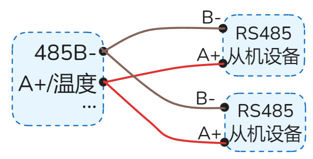 Multiple RS485 - Star Topology (Prone to Interference)
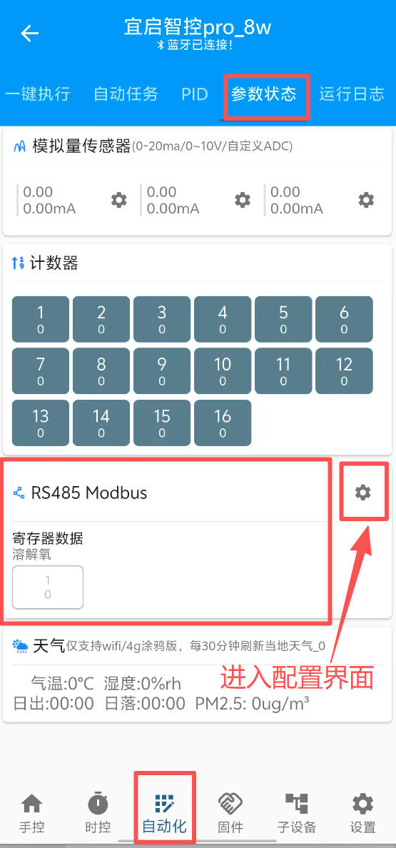
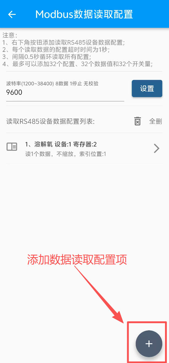
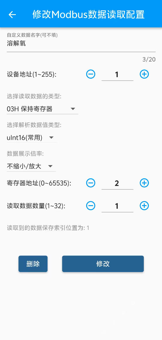
RS485 App Interfaces:
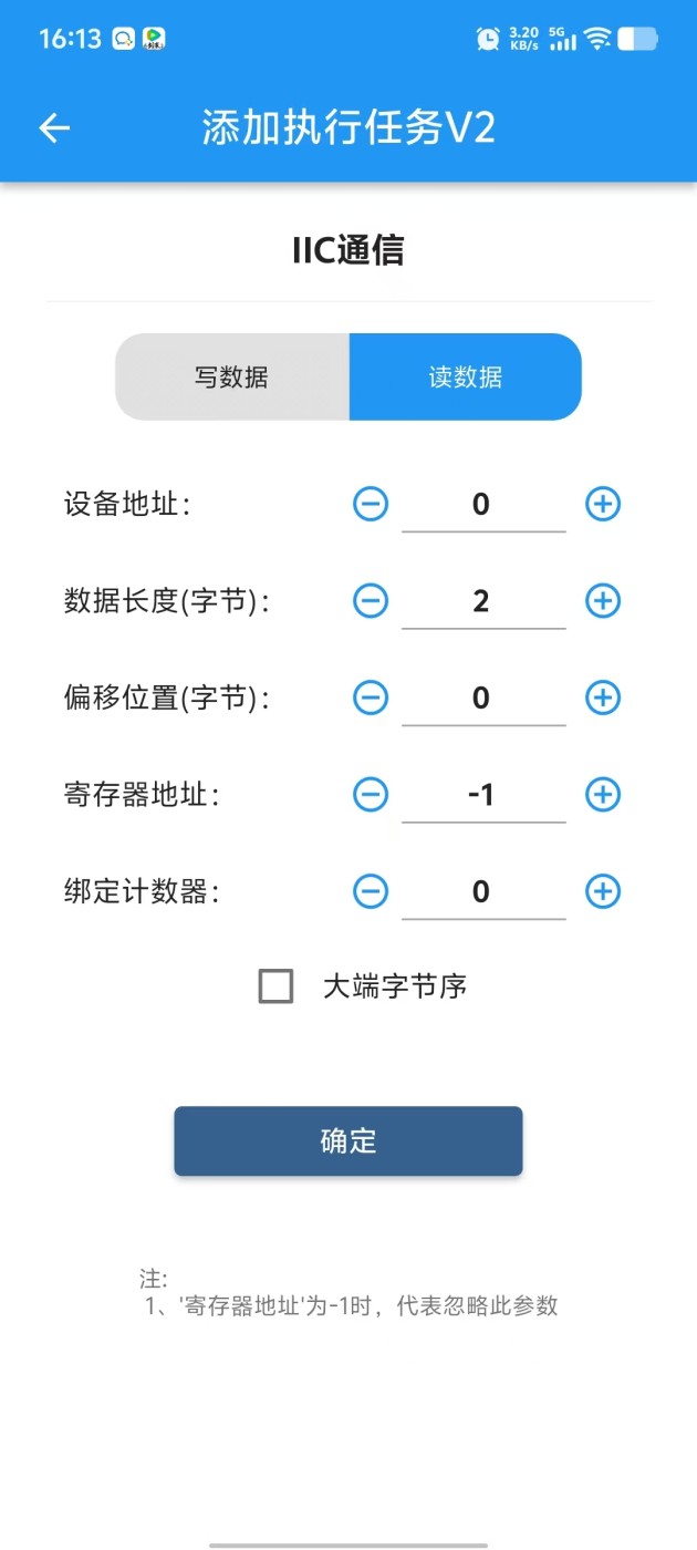
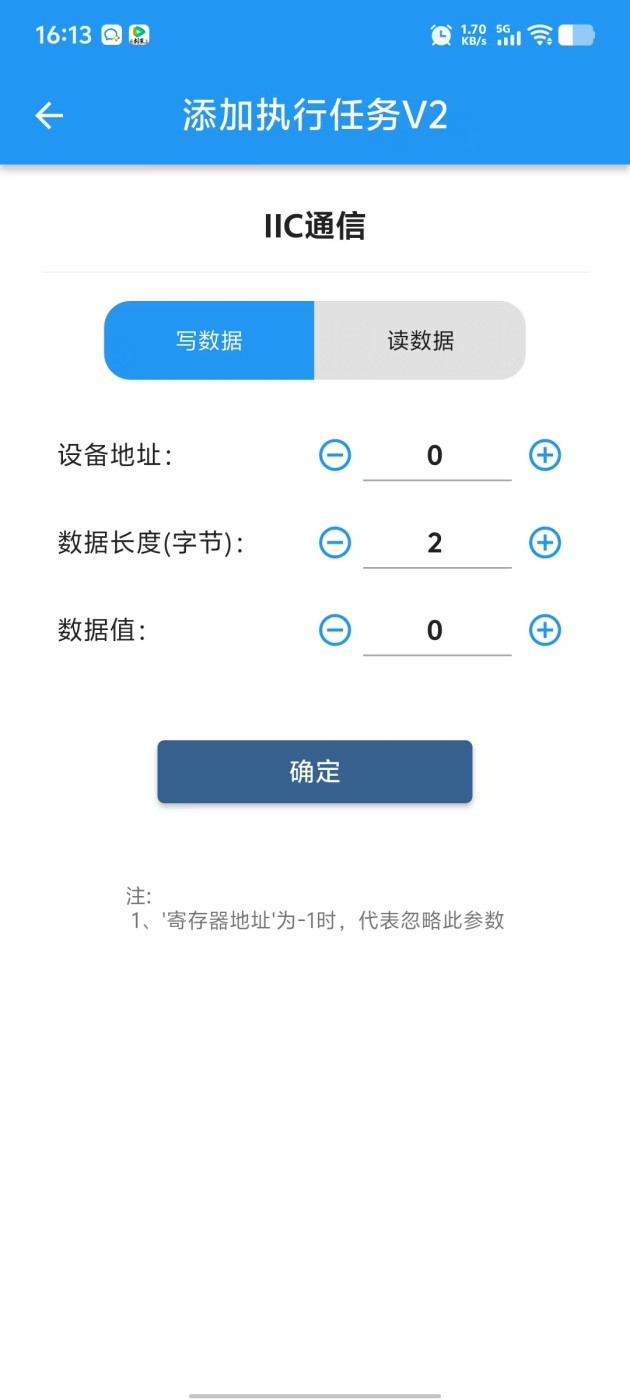
10. IIC Interface
Supports IIC device read/write. Built-in SHT30 temp/humidity sensor and light sensor protocol parsing, plug and play.
IIC communication level is 3.3V.
SHT30 temperature value corresponds to "Temperature 2" in App.
Light intensity data defaults to "Counter 8" in App.
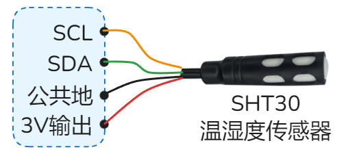 SHT30 Temp/Humidity Sensor
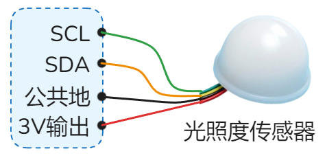 Light Intensity Sensor
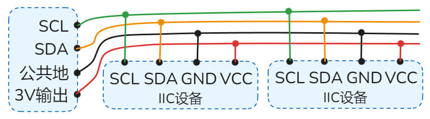 Multiple IIC Sensors
11. 3V Power Output
Provides DC 3V power for low-power sensors. Max load current 30mA.
"·3V Out" terminal is positive, "·GND" terminal is negative.
 DC 3V Output
12. Relay/Switch Output
Relay is an electrically operated switch for circuit on/off control. It is a dry contact output.
Directly controls loads within AC 230V or DC 30V.
Common Uses: Lighting, Water Pumps, Solenoid Valves, AC Contactors, Exhaust Fans, Blowers, Control Cabinet Buttons, DC Motors, etc.
Active (ON): Connected to COM
Active (ON): Closed to NO, Open from NC
Active (ON): Disconnected from COM
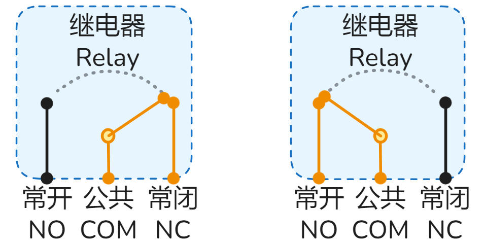 Normal (OFF) (Left) | Active (ON) (Right)
Max Resistive Load: AC 220V/9A (~1.9kW) or DC 30V/9A (~270W).
(Resistive examples: Heaters, Heating wires, Incandescent lamps)
Max Inductive/Capacitive Load: AC 220V/2A (~440W) or DC 30V/2A (~60W).
(Inductive/Capacitive examples: Solenoid valves, AC Contactors, Motors, Pumps, LED Drivers)
Lifespan: Electrical ~100k cycles, Mechanical ~1M cycles.
Coil Power: ~0.36W (5V/72mA).
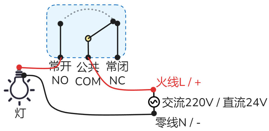 Lighting / Pump / Solenoid Valve
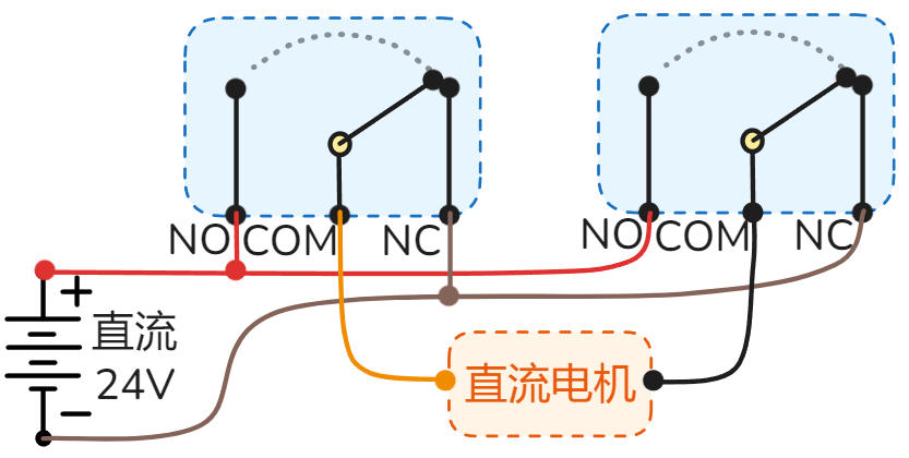 DC Motor Forward/Reverse
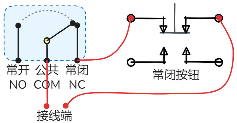 Control Box NC Button Retrofit
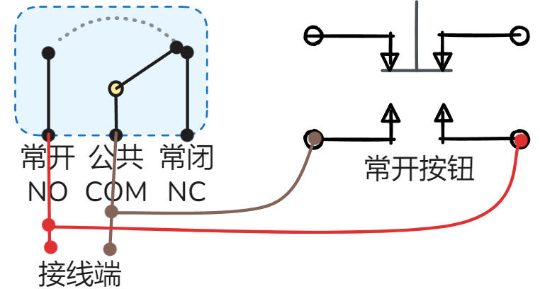 Control Box NO Button Retrofit
13. Relay Indicators
Real-time display of relay status.
·O1 indicates Relay 1 / Switch 1, ·O2 indicates Relay 2, and so on.
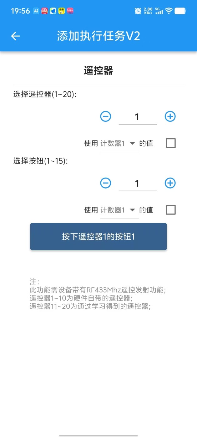
14. RF 433MHz Transmit (Optional)
Optional. Supports sending 433MHz standard RF signals.
Commonly controls: Wireless switches, Garage doors, Gates, Wireless actuators, etc.

15. RF 433MHz Receive (Optional)
Optional. Supports receiving 433MHz standard RF signals.
Commonly receives: 433MHz Remotes, Wireless switches, Wireless sensors, triggering control logic.
Especially suitable for elderly people to control devices via physical remote.

Detailed Specifications
1. Power Interface ·L/36V ·N/GND ·5V ·GND
AC Version (Optional): Connect AC 70-270V (47-63Hz) or DC 100-380V. No L/N distinction.
DC Wide Voltage Version (Optional): Supports DC 9-60V (Power >9W). L/36V terminal connects to positive, N/GND terminal to negative.
DC 5V Standard Version: This port is invalid.
Input Mode: For Standard DC 5V Version. DC 5V (Current >1A), GND connects to negative.
Output Mode: For AC / Wide Voltage Version, this port outputs 5V (Current <100mA), can power small sensors.
· Wiring Examples:
DC Wide Voltage DC 9-60V Power Supply
AC 220V / AC 110V Power Supply
5V Power Supply
2. PWM Output ·P4 ·G4 ·P3 ·G3 ·P2 ·G2 ·P1 ·G1
Uses N-MOS open-drain output, Pn port pulled up to DC 5V. Supports frequency control: 0.025Hz ~ 150kHz, duty cycle control: 0.00% ~ 100.00%, supports linear acceleration and deceleration control.
Port Definition: ·Pn represents PWM output positive, ·Gn represents negative (GND).
Load Capacity: Single channel supports max DC 36V 10A switching load or DC 36V 8A PWM load.
Commonly Used For: DC motor speed control, stepper/servo motor pulse control, servo angle, light brightness adjustment, inverter frequency, valve opening, etc.
PWM Interface Simplified Internal Circuit
LED Brightness / DC Motor Speed Control
Stepper Motor Speed Control
Servo Angle Control
Pn is output voltage positive, Gn is voltage negative, max load current is 10mA.
0-10V Inverter Control Wiring Example
Pn is current output port, Gn is current input port.
0-20mA Device Control Wiring Example
3. PWM Indicators ·P1 ·P2 ·P3 ·P4
Real-time display of PWM1~4 channel output status. Can observe switching and brightness status.
·P1 represents PWM1 channel output status, P2 represents PWM2 channel output status, and so on.
4. USB Power Port ·USB Pwr
Micro USB (Old) / Type-C (New) interface, for convenient 5V power supply to the device, requires current > 1.5A.
Note: Please use high-quality cables to avoid voltage drop due to high resistance, causing insufficient power supply and device malfunction.
5. Reset Button ·Reboot/Reset RST
Device power cycle reboot.
Operation: Short press 7 times continuously: press 1s, release 1s each time.
Function: Restore factory settings, clear all user configurations, restore device to factory default state.
⚠️ Please use this function with caution.
In the App, enter the device details page, click "Reset" or "Reboot" button in the "Settings" interface.
6. Power/Run/Net Indicators ·PWR ·RUN ·NET
Always on indicates normal power supply.
Slow Flash (2s/time): System running normally.
Fast Flash (0.5s/time): Bluetooth connecting (App interacting).
Double Flash (2 fast flashes every 2s): MQTT version network connected.
Always On/Off: Running abnormally, please try to power cycle; if still abnormal, it may be a hardware fault.
Tuya WIFI Version: Fast flash=Waiting for pairing; Always on=Connected; Always off=Connection failed/Connecting.
Tuya 4G / 4G MQTT Version: Slow flash=Connected to base station; Always off=Searching or abnormal.
WIFI MQTT Version: Reserved (No actual function).
7. Switch/NPN/Frequency/Pulse Input ·In1 ·In2 ·In3 ·In4 ·In5 ·In6
Supports Switch, NPN, Frequency, Pulse signal inputs.
Signal Features: Low level / Negative / GND signal is valid.
High Speed Counting: Supports 20kHz frequency input.
Voltage Withstand: Input port withstand voltage 1KV.
Relays, Buttons, Switches, PIR sensors, Limit switches, Photoelectric switches, Magnetic switches, Water level switches, Proximity switches, Infrared beam sensors, etc.
Switch/Button Wiring Example
NPN Sensor Wiring Example
Relay as Input Wiring Example
"3~0 2546"
means Input 3, current frequency 0Hz, accumulated pulses 2546.
8. Analog Input ·Analog1 ·Analog2 ·Analog3
Supports 0-20mA / 0-10V / Custom ADC etc. analog signal inputs.
Applicable Devices: Level transmitters, Pressure transmitters, Current transmitters, Temperature transmitters, Displacement sensors, Wind speed sensors, etc.
0-20mA Gear: Supports 0-20mA, 4-20mA, 0-40mA (New HW)
0-10V Gear: Supports 0-10V, 0-5V, 1-10V, 0-24V (New HW)
Custom ADC Gear: Supports 0-1.5V, 0-3V (New HW) voltage sampling
Device has a 3-position toggle switch on the side for different signal types.
As shown: Analog 1 is Custom ADC, Analog 2 is 0-10V, Analog 3 is 0-20mA.
2-wire 4-20mA Sensor Wiring
3-wire 4-20mA or 0-10V Sensor
4-wire 4-20mA Sensor
Detect 48V Battery (Custom ADC) - Divider to 1.5V
9. RS485/Termperature ·485B- ·A+/Temp
Default Function: Supports DS18B20 temperature sensor, reading corresponds to "Temperature 1" in App.
Note: Sensor cable length suggested ≤ 2 meters; too long may cause interference and read failure.
When RS485 Option Selected: This port acts as RS485 A+ port, DS18B20 function unavailable.
DS18B20 Temperature Sensor Wiring Example
IOTAutoMate acts as RS485 Master, supports reading/controlling various RS485 Slave devices.
Protocol: Modbus RTU
Baud Rate: 1200 ~ 38400bps, Data bits: 8, Stop bits: 1, Parity: None
Read Function Codes: 01H, 02H, 03H, 04H
Write Function Codes: 05H, 06H, 0FH, 10H
Device Capacity: Supports up to 16 slaves. Reads 32 data registers and 32 status bits (Coils/Discrete).
Read Cycle: Auto-cycle read every 0.5 seconds.
Slave Address: Supports address range 1 ~ 31.
Supported Devices: PLC, HMI, Smart Meters, Weather Stations, Relay Modules, Servo Motors, Inverters, PH Sensors, Dissolved Oxygen Sensors, etc.
Correct Wiring Example:
Single Device RS485 Wiring Example
Multiple RS485 Devices — Daisy Chain (Bus) Wiring (Correct)
Not Recommended (Prone to Interferance) Wiring Examples:
Multiple RS485 - T-Junction (Prone to Interference)
Multiple RS485 - Star Topology (Prone to Interference)
RS485 App Interfaces:
10. IIC Interface ·SCL ·SDA
Supports IIC device read/write. Built-in SHT30 temp/humidity sensor and light sensor protocol parsing, plug and play.
IIC communication level is 3.3V.
SHT30 temperature value corresponds to "Temperature 2" in App.
Light intensity data defaults to "Counter 8" in App.
SHT30 Temp/Humidity Sensor
Light Intensity Sensor
Multiple IIC Sensors
11. 3V Power Output ·GND ·3V Out
Provides DC 3V power for low-power sensors. Max load current 30mA.
"·3V Out" terminal is positive, "·GND" terminal is negative.
DC 3V Output
12. Relay/Switch Output ·NO1 ·COM1 ·NC1 ... ·NO6 ·COM6 ·NC6
Relay is an electrically operated switch for circuit on/off control. It is a dry contact output.
Directly controls loads within AC 230V or DC 30V.
Common Uses: Lighting, Water Pumps, Solenoid Valves, AC Contactors, Exhaust Fans, Blowers, Control Cabinet Buttons, DC Motors, etc.
Active (ON): Connected to COM
Active (ON): Closed to NO, Open from NC
Active (ON): Disconnected from COM
Normal (OFF) (Left) | Active (ON) (Right)
Max Resistive Load: AC 220V/9A (~1.9kW) or DC 30V/9A (~270W).
(Resistive examples: Heaters, Heating wires, Incandescent lamps)
Max Inductive/Capacitive Load: AC 220V/2A (~440W) or DC 30V/2A (~60W).
(Inductive/Capacitive examples: Solenoid valves, AC Contactors, Motors, Pumps, LED Drivers)
Lifespan: Electrical ~100k cycles, Mechanical ~1M cycles.
Coil Power: ~0.36W (5V/72mA).
Lighting / Pump / Solenoid Valve
DC Motor Forward/Reverse
Control Box NC Button Retrofit
Control Box NO Button Retrofit
13. Relay Indicators ·O1 ·O2 ·O3 ·O4 ·O5 ·O6
Real-time display of relay status.
·O1 indicates Relay 1 / Switch 1, ·O2 indicates Relay 2, and so on.
14. RF 433MHz Transmit (Optional) ·433MHz Tx
Optional. Supports sending 433MHz standard RF signals.
Commonly controls: Wireless switches, Garage doors, Gates, Wireless actuators, etc.
15. RF 433MHz Receive (Optional) ·433MHz Rx
Optional. Supports receiving 433MHz standard RF signals.
Commonly receives: 433MHz Remotes, Wireless switches, Wireless sensors, triggering control logic.
Especially suitable for elderly people to control devices via physical remote.